Pages

Monday, 30 March 2015

Fluid coupling

Fluid coupling


A fluid coupling is a hydrodynamic device used to transmit rotating mechanical power.It has been used in automobile transmissions as an alternative to a mechanical clutch. It also has widespread application in marine and industrial machine drives, where variable speed operation and/or controlled start-up without shock loading of the power transmission system is essential.

A fluid coupling consists of three components, plus the hydraulic fluid:

>The housing, also known as the shell(which must have an oil tight seal around the drive shafts), contains the fluid and turbines.
>Two turbines (fan like components):
*One connected to the input shaft; known as the pump or impeller, primary wheel input turbine
*The other connected to the output shaft, known as the turbine, output turbine, secondary wheel or runner

The driving turbine, known as the 'pump', (or driving torus) is rotated by the prime mover, which is typically an internal combustion engine or electric motor. The impellor's motion imparts both outwards linear and rotational motion to the fluid.

The hydraulic fluid is directed by the 'pump' whose shape forces the flow in the direction of the 'output turbine' (or driven torus). Here, any difference in the angular velocities of 'input stage' and 'output stage' result in a net force on the 'output turbine' causing a torque; thus causing it to rotate in the same direction as the pump.

Fluid couplings are relatively simple components to produce. For example, the turbines can be aluminum castings or steel stampings, and the housing can also be a casting or made from stamped or forged steel.

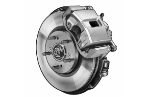
The torque capacity of a two pads disk brake

The torque capacity of a two pads disk brake


The torque capacity of a two pads disk brake can be expressed as

T = μ F r (1)

where

T = torque (Nm)
μ = coeficient of friction
F = force on pad (N)
r = mean radius of pad (m)
Required pad pressure can be expressed as
p = F / A (2)
where
p = pressure (Pa)

A = pad area

TOOL MAKER MICROSCOPE

TOOL MAKER MICROSCOPE


These microscopes are special type of microscopes that are used to create precision tools and measure small distances between two points of a specimen.

A tool maker microscope is a type of a multi functional device that is primarily used for measuring tools and apparatus. These microscopes are widely used and commonly seen inside machine and tools manufacturing industries and factories. These microscopes are also inside electronics production houses and in aeronautic parts factories. A tool maker microscope is an indispensable tool in the different measurement tasks performed throughout the engineering industry.

The main use of a tool maker microscope is to measure the shape, size, angle, and the position of the small components that falls under the microscope’s measuring range. More often than not, a tool maker microscope is outfitted with a CCD camera that has the ability to capture, collect, and store images into specialized computer software. Certain computer aided design software is commonly used for such applications. The image produced by the camera and processed by the software is normally a two dimensional image.


Industrial Automation & Robotics


Industrial Automation & Robotics


Machinery Automation and Robotics provides complete automation and robotic solutions to a wide range of companies Australia wide. With extensive experience in the industry, the company here illustrates some of the benefits of adopting industrial robots for businesses of any size.

Technological innovations have made significant progress in making production and distribution easy and efficient. Whether operating a small company or a big business, there are a number of robotic component solutions available for performing a large number of different functions.

Industrial robots can assist in:

Reducing costs
Improve quality
Increasing production
Address Workplace Health & Safety

Saturday, 28 March 2015

Turbocharger

Turbocharger


Turbocharger is a gas compressor, purposely used for force induction and increase the car performance. With increase of air density pass through the engine, to create more power for the car.

Engine


Engine


Part

1 Compressor Inlet

2 Compressor Discharge

3 Charge air cooler (CAC)

4 Intake Valve

5 Exhaust Valve

6 Turbine Inlet

7 Turbine Discharge

Wednesday, 25 March 2015

Ball Bearing


Ball Bearing


A ball bearing is a type of rolling-element bearing that uses balls to maintain the separation between the bearing races.
The purpose of a ball bearing is to reduce rotational friction and support radial and axial loads. It achieves this by using at least two races to contain the balls and transmit the loads through the balls. In most applications, one race is stationary and the other is attached to the rotating assembly (e.g., a hub or shaft). As one of the bearing races rotates it causes the balls to rotate as well. Because the balls are rolling they have a much lower coefficient of friction than if two flat surfaces were sliding against each other.